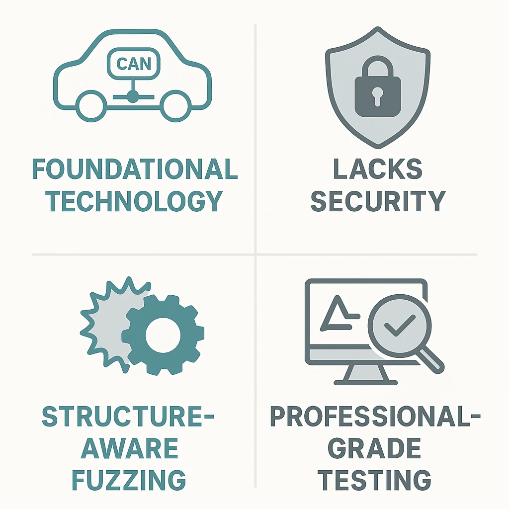
CAN Bus, which stands for Controller Area Network, is a robust vehicle bus standard designed for communication between microcontrollers and devices without a central computer. It was developed by Bosch in the 1980s for automotive applications and is now used in various industries. It's a message-based protocol that allows multiple devices (nodes) to communicate on the same network, offering high resistance to interference and efficient communication over long distances.
Here's a more detailed explanation:
Key Features:
- Message-based: Devices send and receive messages, allowing for efficient data sharing.
- Multi-master: Multiple devices can initiate communication, not just one master device.
- Differential signaling: Uses two wires (CAN high and CAN low) with complementary signals, enhancing noise immunity.
- Fault-tolerant: Designed to withstand some level of error or damage to the network.
- Broadcast communication: Devices send messages to all others, but only the intended recipient acts on it.
How it works:
- Nodes: Devices connected to the CAN bus are called nodes. Examples include Electronic Control Units (ECUs) in a car.
- Message Format: Each message includes an ID (identifying the sender and content) and the actual data.
- Arbitration: If multiple nodes try to transmit simultaneously, a mechanism called arbitration ensures the highest priority message gets through.
- Data Transfer: Data is transmitted serially over the two wires.
- Reception: Each node checks the ID of the message and decides whether to act on it.
Applications:
- Automotive: Connecting ECUs in vehicles for engine control, braking, steering, etc.
- Industrial Automation: Controlling machinery and processes.
- Aerospace: Used in aircraft and spacecraft.
- Medical Devices: In some medical equipment for data transmission.
- Elevators: In some elevator control systems.
Benefits:
- Reduced wiring complexity: Replaces bulky wiring harnesses with a simple two-wire system.
- Improved reliability: Fault tolerance and message prioritization ensure data integrity.
- Cost-effective: The simplicity of the protocol makes it relatively inexpensive.
- Scalability: Easy to add or remove nodes from the network.
Key highlights:
- Data rate: up to 1 Mb/s for classical CAN, and up to 8 Mb/s with CAN FD.
- Identifier-based arbitration: Low IDs = high priority. Nodes transmit bit-by-bit and back off if a higher-priority message is detected.
- Applications: Automotive (engine control, ABS, ADAS), industrial automation, medical equipment, robotics, marine, avionics, and more.
The ISO & RFC Standards Defining CAN
While not an Internet RFC per se, CAN is defined by key standards:
- ISO 11898‑1: Data link layer & framing
- ISO 11898‑2: High‑speed physical layer (up to 1 Mb/s)
- ISO 11898‑3: Low‑speed/fault‑tolerant physical layer (up to 125 kb/s)
- ISO 11898‑4: Time-triggered communication, wake-up, extended features
- Bosch CAN 2.0A/B: Foundational spec (11-/29‑bit IDs) from 1991
- CAN FD (Flexible Data-rate): Defined by Bosch in 2012; up to 64 bytes payload, switchable bit rate
- RFC drafts (e.g., draft‑wachter‑6lo‑can‑00) specify mapping IPv6 atop CAN via ISO‑TP
Anatomy of a CAN Frame
Classic CAN (ISO 11898‑1)
Two formats: Standard (11-bit ID) and Extended (29-bit ID).
CAN FD Additions
- DLC can specify up to 64 bytes.
- Faster data phase after arbitration.
CAN State Machine
A CAN bus (Controller Area Network) doesn't have a single, centralized "state management flow diagram" in the way a microcontroller or operating system might. Instead, it's a network protocol where individual nodes (ECUs or Electronic Control Units) communicate with each other. The state management is distributed across these nodes, with each managing its own internal state related to the CAN communication.
Here's a breakdown of how state management works on a CAN bus:
1. Node Architecture:
- Each node on the CAN bus consists of a CPU, a CAN controller, and a transceiver.
- The CAN controller handles the protocol and message handling.
- The transceiver adapts the signal levels for sending and receiving data on the bus.
2. Message Transmission and Reception:
- Nodes transmit data in frames, and there are different frame types (data, remote, error, overload).
- Each frame contains an ID, data (payload), and error detection (CRC).
- Nodes don't transmit simultaneously, they arbitrate for access to the bus.
- The CAN protocol is designed to be lossless, and arbitration is handled bitwise.
- Nodes synchronize to sample data on the network simultaneously.
3. Error Handling:
- CAN controllers have error counters (TEC and REC).
- These counters track transmit and receive errors.
- Based on these counters, a node can transition between error states (Error Active, Error Passive, Bus Off).
- In Error Active state, a node is considered healthy when TEC and REC are within limits.
- The controller automatically retransmits messages when errors occur.
- Some controllers allow for manual control of error handling.
4. State Transitions:
- Error Active: The node is in a healthy state, participating in normal communication.
- Error Passive: The node is still communicating but is actively participating in error handling.
- Bus Off: The node has encountered too many errors and is no longer participating in communication.
- Nodes can transition between these states based on the error counters.
5. Example of State Changes:
- If a node sends a message and it's not acknowledged, the error counters might increment.
- If the error counters exceed a threshold, the node could transition to Error Passive.
- Further errors could lead to the node becoming Bus Off.
- If the bus recovers, the node might transition back to Error Active.
In essence, state management on a CAN bus is distributed across the nodes, with each node managing its own error states and participation in communication based on error counters and protocol rules.
Use Cases: Real-world CAN Fuzzing
Use Case A: Structure-Aware Fuzzing
- Targeted IDs instead of random fuzz
- 2 real vehicles, 10 critical CAN IDs discovered
- Fewer tests, faster vulnerability discovery
Use Case B: ECU + Sensor Harness
- IMU and sensor harness detect real-world effects
- Found unexpected instrument cluster behaviors
Use Case C: EM Side-channel Guided Fuzzing
- Tracks EM signatures to guide packet generation
- Detects logic faults and DoS
Use Case D: Exploiting Error States
- Flood to force Error Passive/Bus-Off
- Leads to ECU denial-of-service
Penzzer for CAN Fuzzing
How it works:
- Connect via SocketCAN or hardware adapter
- Load DBC for structure-aware targeting
- Monitor error states (TEC, REC)
- Inject CRC errors, boundary values, extreme DLCs
Features:
- Intelligent mutation of IDs and fields
- Live tracking of error states
- Sensor integration (IMU, OBD-II)
- EM side-channel support
- Auto logging and triage
Findings:
- ID 0x100 triggers Bus-Off with bad CRC
- ID 0x200 causes RPM spike detected by IMU
- TEC threshold exceeded from malformed payloads
Why Penzzer?
Want to hear more about Penzzer?
Leave your details and we'll reach out shortly.